
A spin balancer rotates the mounted wheel-and-tire assembly, detects the repeating forces at the spindle, identifies their angular position, and combines that information with the entered rim dimensions and selected weight locations. It then displays the correction mass and position for one or two planes.
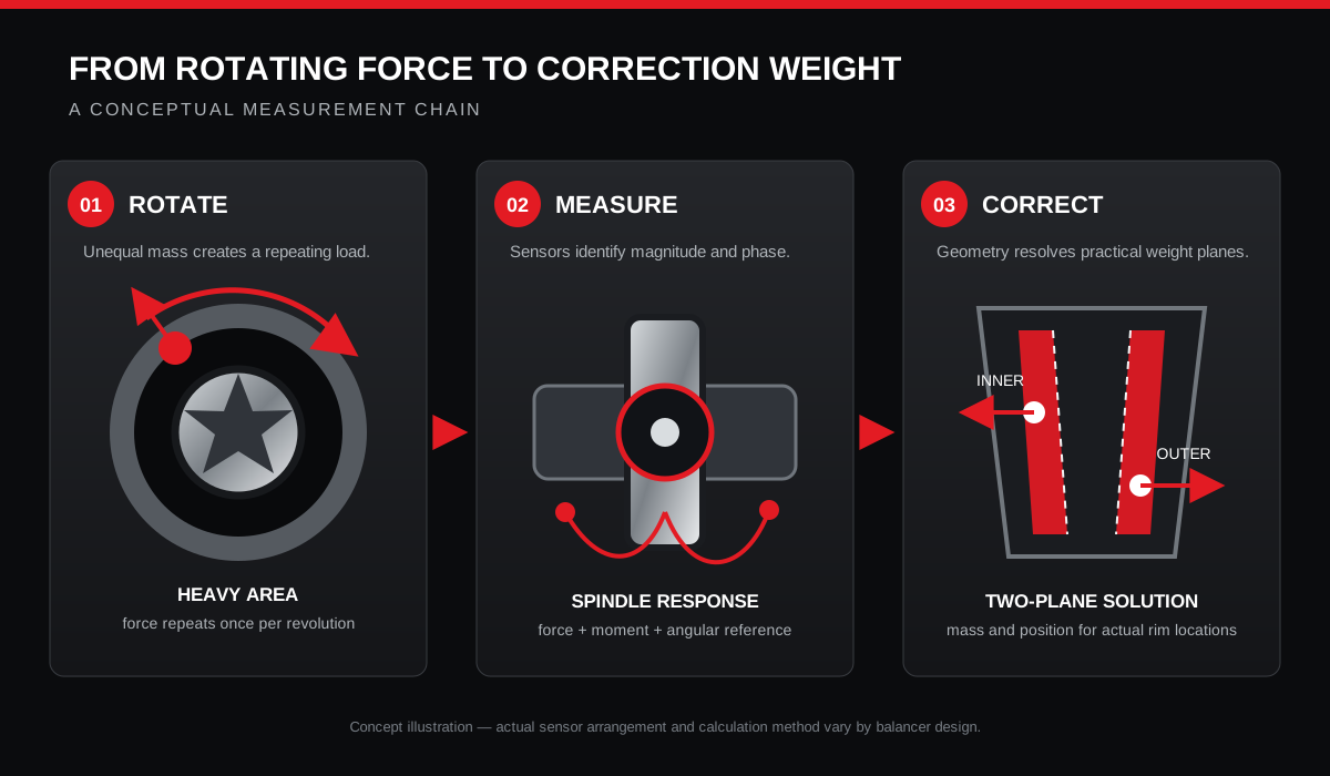
Uneven mass produces a repeating load while the assembly rotates.
The machine identifies the angular location of the imbalance.
Rim geometry defines where correction weights can act.
A check spin confirms the completed correction.
The complete measurement chain
The balancer does not inspect an abstract tire. It measures the complete assembly exactly as it is mounted on the shaft. The wheel center, mounting cone or flange adapter, contact faces, shaft and clamping force therefore become part of the measurement.
During the spin, spindle sensors detect the changing load produced by unequal mass distribution. A position reference tracks where the assembly is in its rotation. The control system compares the measured signal with the wheel dimensions and balance mode, then calculates a practical correction.
Force, speed and phase
A small heavy area located away from the rotational axis creates centrifugal force as the wheel turns. Conceptually, the force follows F = m × r × ω²: it increases with imbalance mass, its distance from the axis and the square of rotational speed. This explains why a modest imbalance can become much more noticeable as road speed rises.
The balancer needs both magnitude and phase. Magnitude indicates how much correction is required. Phase identifies where around the wheel it must act. The machine can measure at a controlled shop speed because its sensors, calibration and software interpret the repeating force signal; it does not need to reproduce every road speed.
Why wheel dimensions matter
| Input | What it represents | Effect of an incorrect value |
|---|---|---|
| Distance | Axial position of the correction plane relative to the machine | The requested correction can be assigned to the wrong plane. |
| Diameter | Radius at which the selected weight will act | The calculated mass may not produce the intended correcting moment. |
| Width or second-plane position | Separation between inner and outer correction locations | Couple correction can be inaccurate or difficult to verify. |
| Balance mode | Actual clip-on or adhesive weight locations | The display may guide the operator to locations different from where weights are installed. |
Automatic data entry reduces manual input, but the technician still needs to confirm that the selected mode matches the actual wheel and permitted weight locations.
From sensor signal to correction planes
Static imbalance produces an up-and-down shaking force. Couple imbalance produces a side-to-side rocking moment. Dynamic imbalance is the combined condition. A modern two-plane balance resolves the measured signal into corrections at the selected inner and outer locations so both effects can be reduced.
A wheel can show little static imbalance and still have a significant couple. That is why placing one weight at the wheel centerline is not equivalent to a two-plane correction on a wide passenger-vehicle wheel. Adhesive weights can provide two-plane correction when their exact positions are measured and the matching alloy mode is selected.
A repeatable balancing workflow
- Inspect the tire and wheel for damage, foreign material and obvious runout.
- Remove loose or previous correction weights when beginning a fresh diagnosis.
- Clean the shaft, adapters, wheel center and mating surfaces.
- Select the centering method that matches the wheel design and mount the assembly consistently.
- Measure or enter distance, diameter and width, then select the mode that matches the intended weight locations.
- Lower the guard and complete the measurement spin according to the balancer procedure.
- Rotate to each indicated position and install the specified clip-on or adhesive weight accurately.
- Complete a verification spin and correct any meaningful residual.
- When readings do not repeat, remount the assembly before adding or chasing more weight.
What balancing cannot correct
Balancing changes mass distribution. It does not straighten a bent rim, make an out-of-round tire round, remove radial or lateral runout, correct tire force variation, repair a damaged hub or change wheel alignment angles.
A vehicle can still vibrate after a verified balance because the assembly mounts differently on the vehicle, a tire changes shape under load, or another rotating, steering or suspension component is involved. Use runout measurement, mounting checks and vehicle diagnosis rather than assuming every speed-related vibration needs more wheel weight.
Frequently asked questions
Why does the balancer need rim diameter and distance?
Correction effectiveness depends on where the weight acts. The machine uses the entered geometry to translate the measured imbalance into a mass at the selected rim location.
Can a wheel be statically balanced but dynamically imbalanced?
Yes. Opposing imbalance across the inner and outer planes can create a rocking couple even when the assembly has little net static imbalance.
Why can the reading change after the wheel is remounted?
The wheel may not return to the same center or seating plane. Clean the interfaces, verify the adapter and use a controlled remount test before changing the correction.
Does a balancer correct radial runout?
No. Runout is geometric variation in the wheel or tire surface. Correction weight changes mass distribution, not shape.
Why is a verification spin required?
It confirms that the weights were installed in the correct planes and angular positions and that the assembly remained mounted consistently.
TreadPlus technical learning reference · Published July 21, 2026. Follow the wheel, tire, balancer and vehicle manufacturer procedures for the application.